Describe How the Processor Using the First Four Registers Listed
The size of this register is 2 or 4 bytes. Output Register 8 bits FGI.

Portable Apple Ii On An Avr Apple Ii Electronics Mini Projects Apple
Describe how the function can be performed more efficiently by also employing IEN.
. And once 8-bit data enters the INPR then FGI. In this first design every instruction begins execution on one clock edge and completes execution on the next clock edge. Interrupt Enable 1 bit Keystroke input from the teletype and printer output to the teletype are controlled by the IO module.
When there are 4 jobs the CPU is round-robin among the four as is the IO. Output register 8 bits FGI. Current Instruction Register CIR - this holds the current instruction being executed.
Input Register 8 bits OUTR. It is a special purpose register with size one byte or two bytes. These are numbered as R0 R1 R2Rn-1 and used to store temporary data during any ongoing operation.
Input flag 1 and the processor transfer data of INPR to AC and change FGI. Describe how the processor using the first four registers listed in the problem can achieve IO with the teletype. Output Register 8 bits.
Interrupt Enable 1 bit. Interrupt enable 1 bit Keystroke input from the teletype and printer output to the teletype are controlled by the IO module. Interrupt Enable 1 bit Keystroke input from the Teletype and output to the printer are controlled by the IO module.
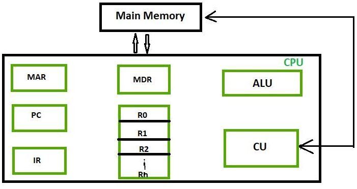
The following registers are contained in the processor and connected directly to the system bus. The first four AX BX CX and DX are common use registers and can also be used as 8 bit registers if used in such a way it is essential to refer to them such as. First In and Last Out FILO.
Registers are small amounts of high-speed memory contained within the CPU. Code or algorithm descriptions at the level of pseudo-code would be appropriate as part of this discussionanswer. Input flag 0 it will be accepted by INPR.
Output Flag 1 bit IEN. Input Register 8 bits OUTR. The following registers are contained in the CPU and connected directlyto the system bus.
Its content can be accessed by assembly programming. Input Register 8 bits. The following registers are contained in the CPU and connected directly to the system bus.
Consider a computer system that contains an IO module controlling a simple keyboardprinter Teletype. Output Flag 1 bit. Register are used to quickly accept store and transfer data and instructions that are being used immediately by the CPU there are various types of Registers those are used for various purposeAmong of the some Mostly used Registers named as AC or Accumulator Data Register or DR the AR or Address Register program counter PC Memory Data Register MDR Index.
The following registers are contained in the processor and connected directly to the system bus. Memory Address Register MAR - this holds the RAM address you want to read to or write from. IO CPU IO CPU Job3.
Output flag 1 bit IEN. Describe how the CPU using the first four registers listed in this problem can achieve IO with the teletype. A brief description of most important CPUs registers and their functions are given below.
Input Register 8 bits OUTR. Interrupt Enable 1 bit. Input flag 1 bit FGO.
Input Register 8 bits Output Register 8 bits Input Flag 1 Bit Output Flag 1 Bit Interrupt Enable 1 Bit. The following registers are contained in the CPU and connected directly to the system bus. The main job of the CPU is to execute programs using the fetch-decode-execute cycle also known as the instruction cycle.
Modern CPU architectures tends to use more GPR so that register-to-register addressing can be used more which is comparatively faster than other addressing modes. When CPU wants to store some data in the memory or reads the data from. Output Register 8 bits FGI.
This register holds the address of memory where CPU wants to read or write data. The registers you should know about include. The following registers are contained in the processor and connected directly to the system bus.
Memory Address Register MAR. Describe how the function in a is inefficient and how it can be performed more efficiently by also employing IEN. Input Flag 1 bit FGO.
Input register 8 bits OUTR. General Purpose Registers. This means the jobs are interleaved as.
Consider a computer system that contains an IO module controlling a simple keyboard printer Teletype. Input Flag 1 bit FGO. The Flag register is used to indicate occurrence of a certain condition during an operation of the CPU.
Output Register 8 bits FGI. The instruction register fetches instructions from the program counter PC and holds each instruction as it is executed by the processor. This nomenclature is also appropriate to the BX CX and DX registers.
Internal registers include the instruction register IR memory buffer register MBR memory data register MDR and memory address register MAR. This cycle begins as soon as you turn on a. Input register to 0.
Consider a computer systemthat contains an IO module controlling a simple keyboardprinter teletype. IO CPU IO CPU Job2. AH is the high and AL is the low bytes of the AX register.
The Input flag is set when an 8-bit word enters the input register from the teletype. They are used by the processor to store small amounts of. The following registers are contained in the CPU and connected directly to the systembus.
Output Flag 1 bit IEN. Most new computer systems on the market today are quad-core but CPUs with even more. Each register performs a specific function.
Input Flag 1 bit. Using two processors is referred to a duo-core and using four processors is referred to as a quad-core. Program Counter PC - this holds the address of the next instruction to be fetched and executed.
Output Flag 1 bit IEN. IO CPU IO CPU Job4. Input Flag 1 bit FGO.
The Stack Control Register is used to manage the stacks in memory. IO CPU IO CPU A job can execute for one cycle T then it must wait for T before doing another cycle. The CPU has four internal registers each of 16 bits.
Sections 43 and 44 describe a simple implementation that uses a single long clock cycle for every instruction and follows the general form of Figures 41 and 42. Registers are the most important components of CPU. The Output flag is set when a word is printed.
Describe how the CPU when using the first 4 registers listed above can achieve IO with the Teletype.

Listed Below Are The Top 10 Best Motorola Droid Turbo 2 Cases And Covers Description From 1mtb Com I Searched For This On Bing Com I Case Cover Motorola Case

Allshopathome Best Price Comparison Website Compare Prices Save All Shop At Home Tea Maker Electric Tea Kettle Breville
Different Classes Of Cpu Registers Geeksforgeeks

Work Flow Of Arm 7 Computer Processors Computer Processor Central Processing Unit

Program Status Register Psw Of 8051 The 8051 Has A 8 Bit Psw Register Which Is Alsoknown As Flag Register In The 8 Bit Register Only Status Words Registered

Buses Connecting I O To Processor And Memory

Zus Is A Smart Car Finder And Usb Car Charger It Charges Up Your Mobile Devices At Their Max Speed And Finds Cyber Monday Free Shipping Charger Car Smart Car
Cortex M3 Technical Reference Manual R2p0

8 Bit Computer Ram 8 Bit Ram Computer
Types Of Cpu Top 6 Processors Of Cpu With Explanation

Vector Processor An Overview Sciencedirect Topics

Various Instructions Code Formats Addressing Mode Segmentation Direct Address

13 Best Heavy Duty Mixer Grinder Juicer Under 7000 Rupees Juicer Grinder Mixer

Buses Connecting I O To Processor And Memory

How To Identify Pressed Switches From A Group Of Switches Using 74165 And Arduino Mega Read More At Http Www Arduino Arduino Projects Electrical Projects

Spss Data Editor Data View Data Direct Marketing Spss Statistics

Esp8266 5 Internet Connected Switch Internet Switch Esp8266 Projects Arduino
Cortex M3 Devices Generic User Guide
Architecture Of A Cpu


Comments
Post a Comment